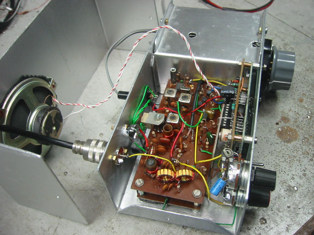

Described here is a “ bare bones “ QRP CW transceiver for the twenty meter band using common cheap components, most of the components used came from the junk box. Four watts output is produced along with QSK. Although a fairly simple transceiver, it performs very well indeed. The only controls on the set are; Tuning, RIT and Gain. The receiver section is a single conversion superhet and consists of a two pole antenna bandpass filter followed by a dual gate mosfet RF preamplifier with gain control. The purpose of this stage is to make up for the insertion loss of the SBL-1 DBM and to provide minimal loading on the bandpass filter thus maintaining a reasonable Q. A mosfet was chosen due to its good strong signal performance. The source of the mosfet is held at approximately 2.5 volts by D1,D2 and R3, thus its G2 voltage can go negative with respect to the source giving a much greater gain range. The receiver mixer is a double balanced diode ring ( SBL-1 ), again this was chosen for its excellent strong signal performance and low IMD3 products, low side LO injection is used with this mixer. IF from the mixer is then fed into a post mixer preamplifier consisting of Q2, this transistor is heavily biased ensuring good signal performance. The output from Q2 is fed into a four pole crystal ladder filter using 8MHz cpu crystals ( I calculated the capacitor values using a “filter calculator” found on the internet ). Measured response of the filter is very close to the predicted values, approximately 700Hz -3dB bandwidth and the Fo = 7.9987 MHz. The crystals were matched to within plus or minus 30Hz of each other. I bought a bag of one hundred 8MHz crystals for £2.50 ( inc. pp ) from Ebay, and I found plenty of matched crystals amongst them. A cascode IF preamplifier using a CA3028A follows the crystal filter, this is a old chip now but I had a few of them in the junk box. The “bottom” transistor of the cascode pair ( see manufactures data sheet ) is used for gain control. If you do not have one of these , it is a simple task to make a discrete cascode preamplifier using a couple of IF type transistors ( BF173's etc.).Being as AGC is a mere operating convenience, none is used in this bare bones set. Amplified IF is then fed into a product detector using a NE602. Balanced audio is taken from pins 4 and 5 of the NE602 and fed to LM386 audio power amplifier. In use the receiver is useable down to signals in the region of 1 - 2 uV at the antenna socket.
The VFO consists of a series tuned colpits oscillator ( Jfet Q1 ) followed by a Jfet buffer and two bipolar transistor buffers. Q3 buffer produces 5 milliwatts output which is fine for driving the SBL-1 local oscillator input. Approximately 2 milliwatts is produced by Q4 stage which drives the TX circuit and frequency display. The main tuning inductor L1 is wound on a spent ceramic cartridge fuse and covered with a thin film of Areldite. A planetary reduction drive is used with the VFO tuning capacitor. With the values shown, VFO coverage will be approximately 5.990MHz to 6.120MHz ( giving a 20M coverage of 13.990 MHZ to 14.120 MHz i.e. all of the CW section of the band ). Greater coverage can be had by experimenting with the coil turns and tuning capacitor value. Stability and drift is excellent, after an initial warm up period of 15 minutes, drift is no more than 30Hz in one hour, though no doubt this will vary from builder to builder and components used.
The transmitter comprises of a NE602 configured as a double balanced transmit mixer and oscillator, keying is achieved by switching the HT to this chip. A 2 pole bandpass filter precedes a three stage PA. Q1 is biased in class A, Q2 and Q3 are biased in class C making a very efficient power amplifier, for 4 watts out the current drain is approximately 0.7A. A simple pie network is used to transform the output impedence of Q3 output to 50 ohms. For Q3 I used the PA output transistor from an old europa VHF pmr set but any CB type transistor will work OK here. A diode switch ( D1,D2 and D3 ) is used to isolate the receiver during transmit periods and providing full QSK. The PA stage is followed by a 2 pole low pass antenna filter. The note produced by the transmitter is pleasant, no chirp or key clicks. No side tone oscillator is necessary here as you will hear your actual transmission from the receiver, the side tone is a little "clicky", if this bothers you then a seperate side tone osc may be employed.
For the frequency display VK3BHR pic counter was utilized – a excellent project using a PIC and a LCD display. All of the source code and asm files are freely available on his website to enable you to blow hex code into the PIC.
Barry Zarucki M0DGQ
HOME